Kawasaki’s LNG Tank Business: Our Source of Energy
Liquefied natural gas (LNG) is low in CO2 emissions and is being used more and more for city gas. To supply LNG stably, cryogenic LNG tanks are essential. Kawasaki is working on innovations in design, manufacturing and construction technology as part of a tank construction project at the largest level in the world.
World-scale In-ground Tanks and Insulation Wall Technology
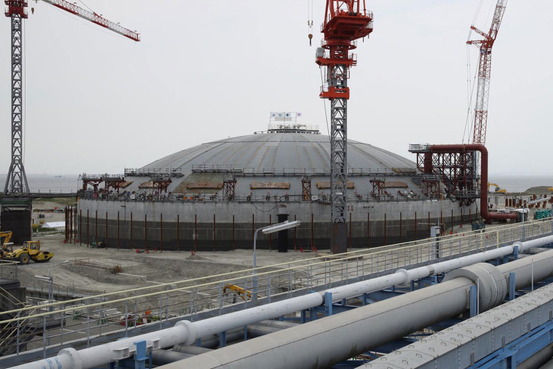
It takes 30 minutes to go down the Chita Peninsula from Nagoya by train. On the beach overlooking the Ise Bay lies the Chita Midorihama Works of Toho Gas, a major company for city gas. Two in-ground LNG storage tanks are already in operation, but next to them a third tank has appeared. Toho Gas has been building this tank to further improve the stable supply of city gas. The in-ground tanks keep the scenery in mind. All that is visible from above ground is a dome-shaped roof.
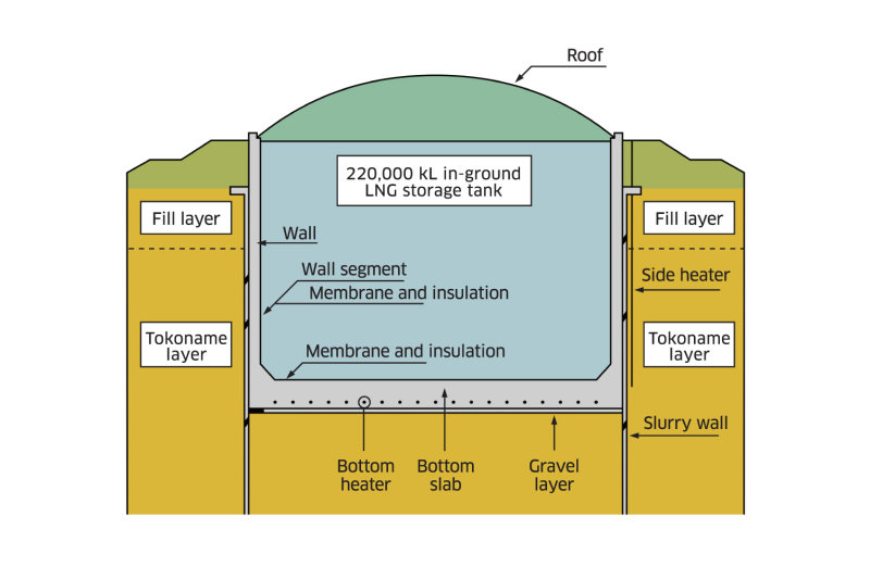
The tanks are cylinders of thick concrete. Their inner diameter is approximately 75 meters, and their depth is approximately 50 meters. Their capacity is 220,000 kL, which makes them some of the largest in the world. Kawasaki is responsible for the construction of many aspects of this project, including the roof and insulation.
June 1, 2015. From the bottom of the cylinder, a roof like a pot lid about 1,000 tons in weight quietly rises. Its speed is 20 centimeters per minute. The roof was made at the bottom of the cylinder to make it airtight with precision machining. A small air pressure was fed in to float it up, using a method called air raising. Thus, the roof floats up to the surface. It is a spectacular sight, with no help from cranes at all.
Masahiro Tsunekawa, a project manager at Kawasaki, explains, “we calculate the center of gravity of the roof and put weights on it based on that before we float it up. This time, the weight distribution of the roof was complex and made the center of gravity difficult to figure out, so it was a relief when things finished all right. We hold the roof temporarily with a piece like a wedge when it gets above ground.”
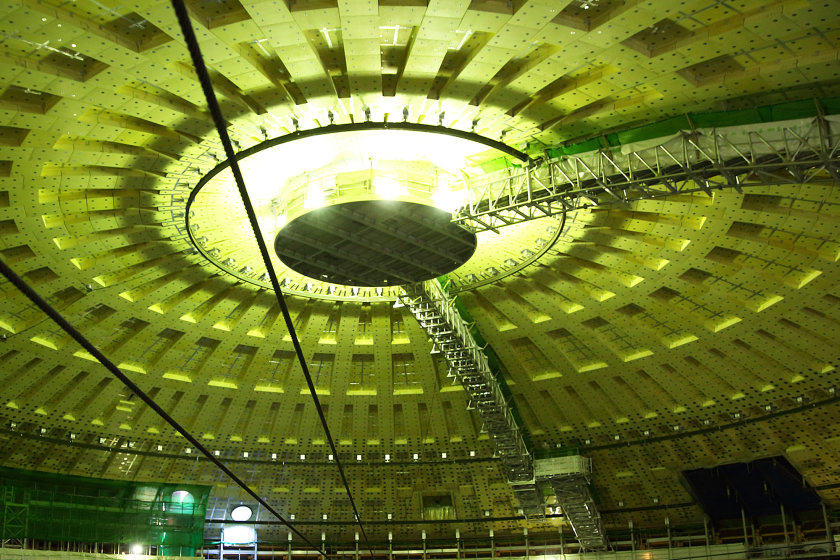
The floating that began at 8 a.m. ends at 1:30 p.m. The roof of about 1,000 tons has been lifted about 50 meters in only five and a half hours. In the tank with the roof on it, almost everything is exposed concrete, yet the slight amount of light and illumination shining in creates a mystical green atmosphere.
“Now that the roof is up, it’s time for the real construction,” says Takeshi Maeda, director of construction of Tank 3 of the Toho Gas Chita Midorihama Works, who is responsible for on-site work on behalf of Kawasaki. To ensure liquid- and gas-tightness, work begins to install insulation on the bottom and sides and thin stainless steel sheets called membranes. By the end of the year, the concrete cylinder will have transformed into a glistening silver chamber. The design, manufacturing and installation of the membrane are where Kawasaki really gets to show off the technology it has built up.
Stainless Membrane 2 Millimeters Thin Achieves Insulation with Waves
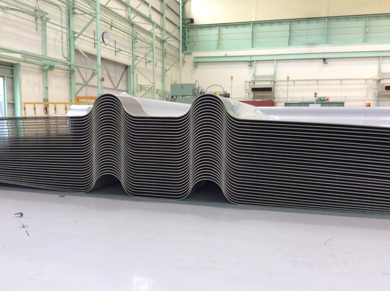
By the time the roof rose over Tank 3, Kawasaki’s Harima Works (in Harima, Hyogo Prefecture) was coming to the last stage of production of the membrane panels. The membranes are stainless steel sheets only 2 millimeters in thickness. Stainless steel has the advantages that it does not corrode and it stays strong even at extremely low temperatures. But the shape of these membranes is unusual. There are lines and grids of round protrusions. This wavelike shape and pattern, in fact, represents the most advanced engineering of the manufacturer working on the cryogenic LNG tank.
LNG liquefies at –162 degrees Celsius. No refrigeration is used in the tank; the LNG is stored as is. Cold insulation is used to maintain the temperature, but Tsunekawa says, “At such low temperatures, stainless steel shrinks a lot, about 3 millimeters per meter, 20 centimeters overall if the inner diameter of the base is 75 meters.” The waves absorb this shrinkage to prevent liquid from leaking through the membrane.
The Kawasaki membrane has “rotary constriction”: When the stainless steel shrinks, the surrounding waves open up, and a flat plate surrounded by waves starts to rotate around. The stainless steel sheets receive little load themselves and resist fatigue. They are highly rigid even under the weight of the LNG. Tsunekawa says proudly, “The Kawasaki membrane can even withstand a tank of depth in the 90-meter class.” The waves are an original Kawasaki technology which earlier engineers thought of when they noticed the waves on the roofs of houses. The technology dates back to when Kawasaki got involved in the LNG tank business about 35 years ago.
To decide where to apply waves on a membrane, detailed analysis is performed for each place it is to be applied. For example, the temperature difference between above and below liquid surface in the tank is examined. In this case, for Tank 3 of the Toho Gas Chita Midorihama Works, membranes were prepared in 112 different shapes, the smallest 68 centimeters square, the largest 1.7 by 3 meters. There are 7,900 membranes in total. There are 23 dies to make the waves.
“The large number of dies is a manufacturing challenge. Precise processing technology is required,” says Shinji Kawabata, who leads a membrane production team at Kawasaki.”
“When there are many dies, there are many variations in the shape and precision of the waves. There can easily be gaps when the membranes are joined into a panel. Therefore, we take into consideration the downstream process of joining the individual panels as we specify quality requirements, which we manage strictly.”
Panels Made Faster, with No Scratches Deeper than 35 Micrometers
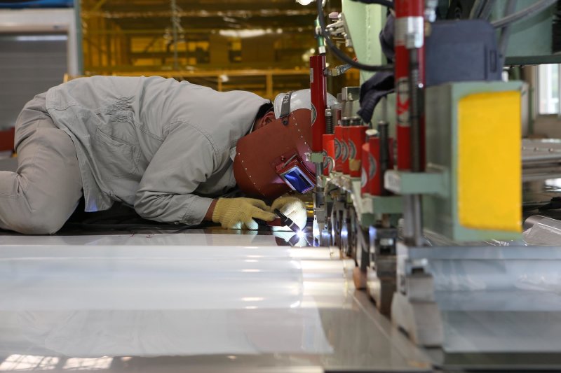
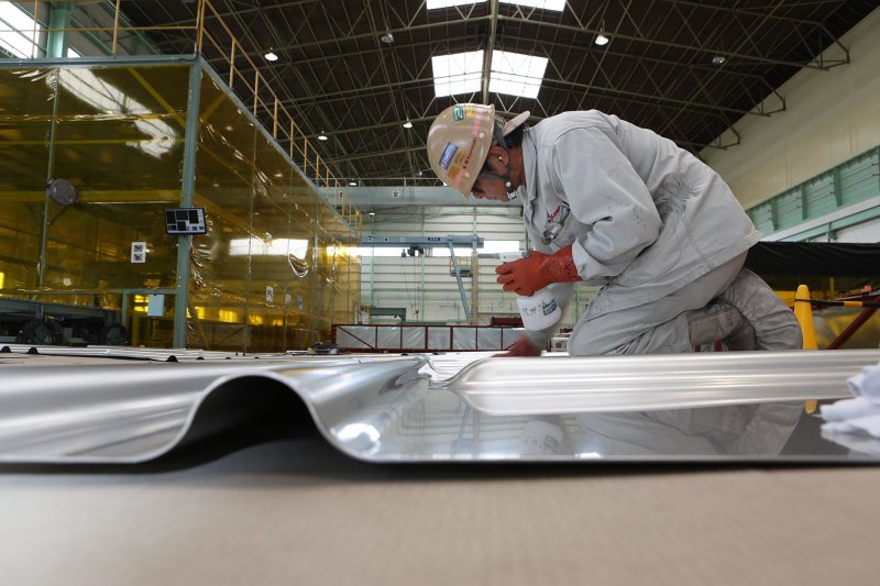
The membranes are welded together on a new line at the Harima Works into large panels (blocks). The trick in the beginning is to control the gaps when multiple membranes are temporarily fastened (fitted) for welding. Gauges are inserted to keep the gaps within 0.3 millimeters in temporary fitting, and then the membranes are sent to the welding process. This is where the skill of experts is shown.
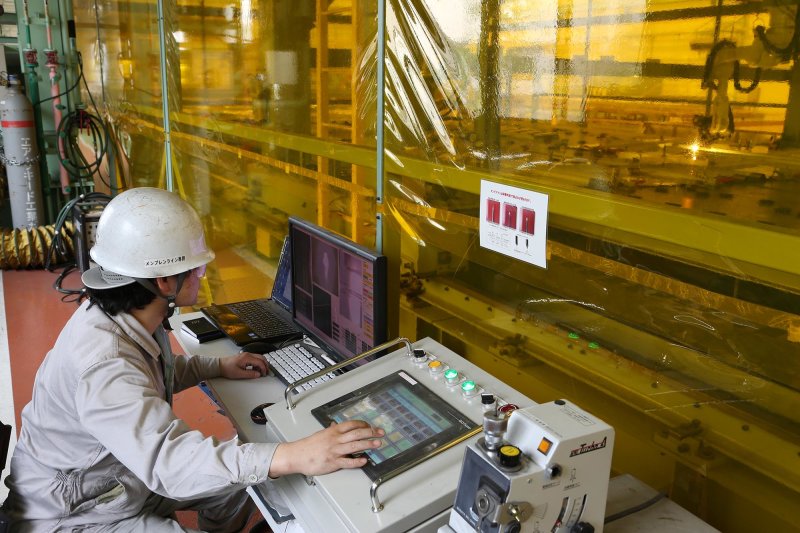
Automatic welding robots were developed for this project jointly among organizations including the Corporate Technology Division at the Head Office and the Production Center at the Harima Works. The joining of the membranes is checked, and lasers are used to determine the appropriate the welding lines.
The tanks are cylindrical, but the parts where the walls and floors contact are not vertical, but diagonal. This technique increases the strength of the tanks, but it also makes the shape of the membranes more complicated. The walls of the tanks are not perfect circles, but have 80 sides at 4.5-degree angles. The precise welding of robots was necessary to assure the precision of the design.
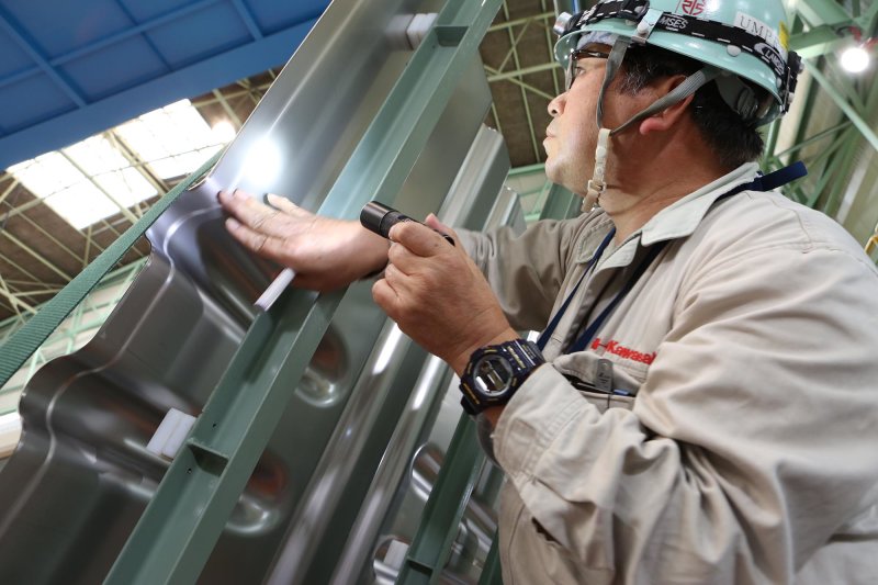
Even after welding, there is still another major challenge for the membranes. It is confirming surface precision. If a membrane has a scratch on its surface, the scratch may grow into a leak because of temperature and pressure changes from liquid going in and out. Therefore, it is specified that surface scratches may not be deeper than 35 micrometers (0.035 millimeters). If they are deeper, they must be repaired.
“With the help of the Quality Assurance Department, we have introduced new inspection equipment that measures the depth of scratches by camera. It was a major engineering priority for us in this project, along with making welding automatic and developing a digital method of measuring the depth of surface scratches,” says Kawabata.
The team paid such attention to how they joined membranes into a panel because they had a new mission to shorten construction time and assure stable quality in on-site construction. Maeda explains, “We had to eliminate risks such as of on-site defects and complete a high-quality product quickly. This will allow our client to start up the equipment sooner and build a stable supply system sooner.”
Membrane panel manufacturing process
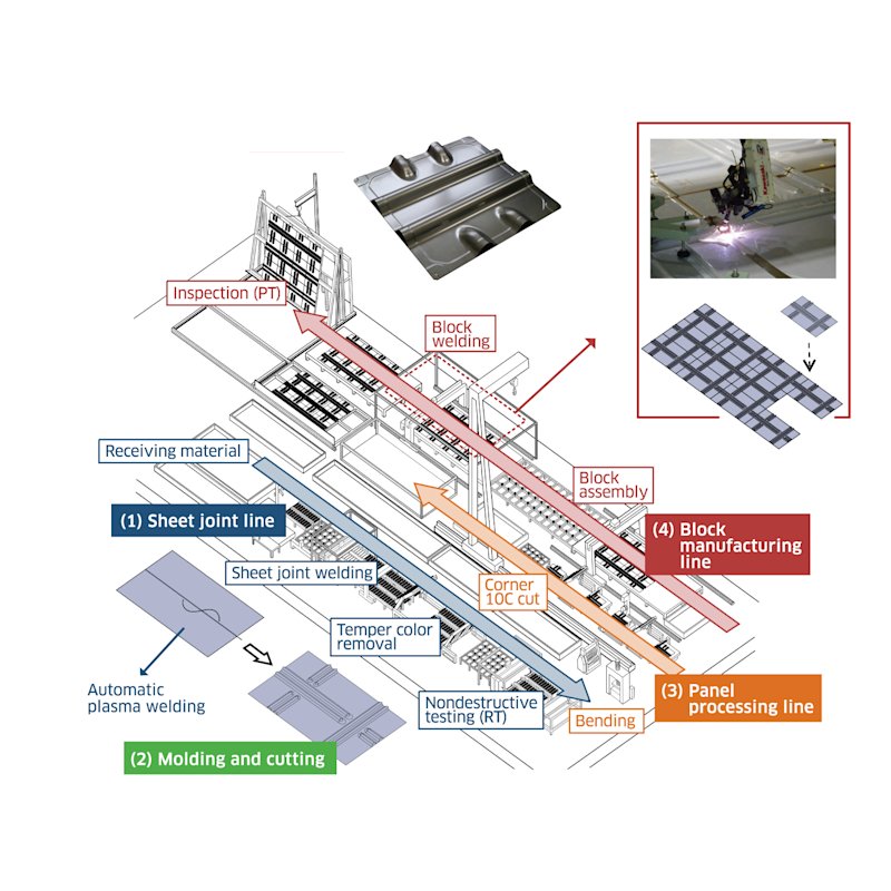
Several membranes of different shapes, 2 millimeters thick (Photo A), are joined into a panel according to the place for application. They are temporarily fitted (Photo B), welded with an automatic Welding Machine (Photo C), polished up (Photo D), and inspected for scratches with a specially developed tester (Photo E)
Kawasaki Works Together to Develop a New Welding Machine
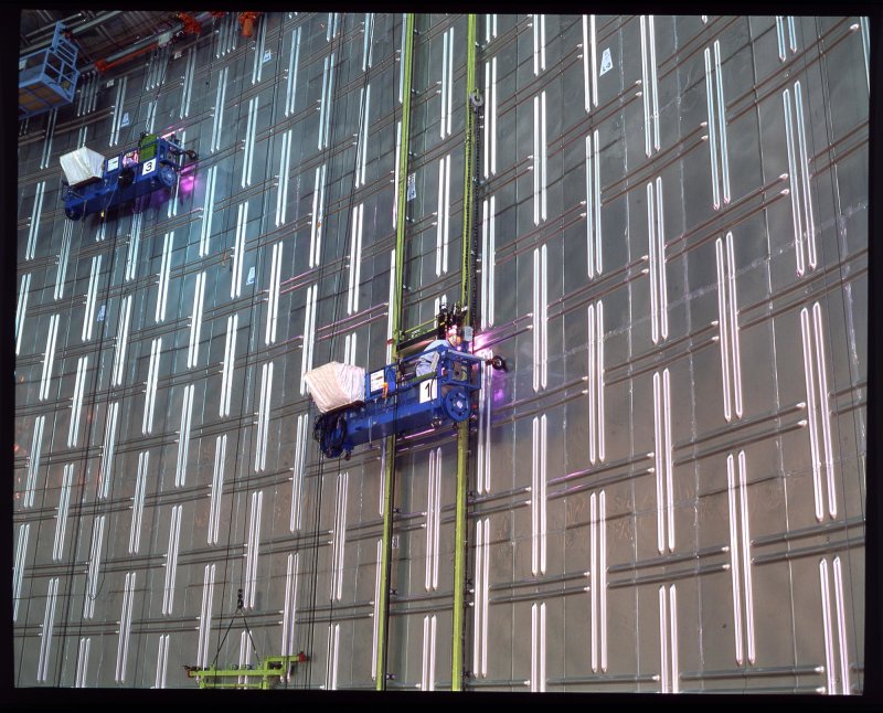
When one looks back at the construction site, by the wall of the tank, there are 30 gondolas suspended which each seat two people and carry a newly developed automatic Welding Machine. The membrane panels assembled at the Harima Works are being carried up and installed. When the wall is finished, work will move on to the floor, and inspection of the welding will begin at the start of 2016. Workers will check that there are no ammonia leaks, check surface precision, and check various other things.
In the final stage, workers in gondolas will look as if they are polishing mirrors. Then what will be seen is a realization of the strict evaporation standards demanded of LNG tanks. The tank will be so well-insulated from heat that it would take three years for all of the contents to evaporate after it is filled.
Maeda says, “On this project, all of our departments really worked together, from design to manufacturing to construction to R&D. I have worked on five LNG tank construction projects, but I have never before seen Kawasaki show its strength together as it has on this one.”
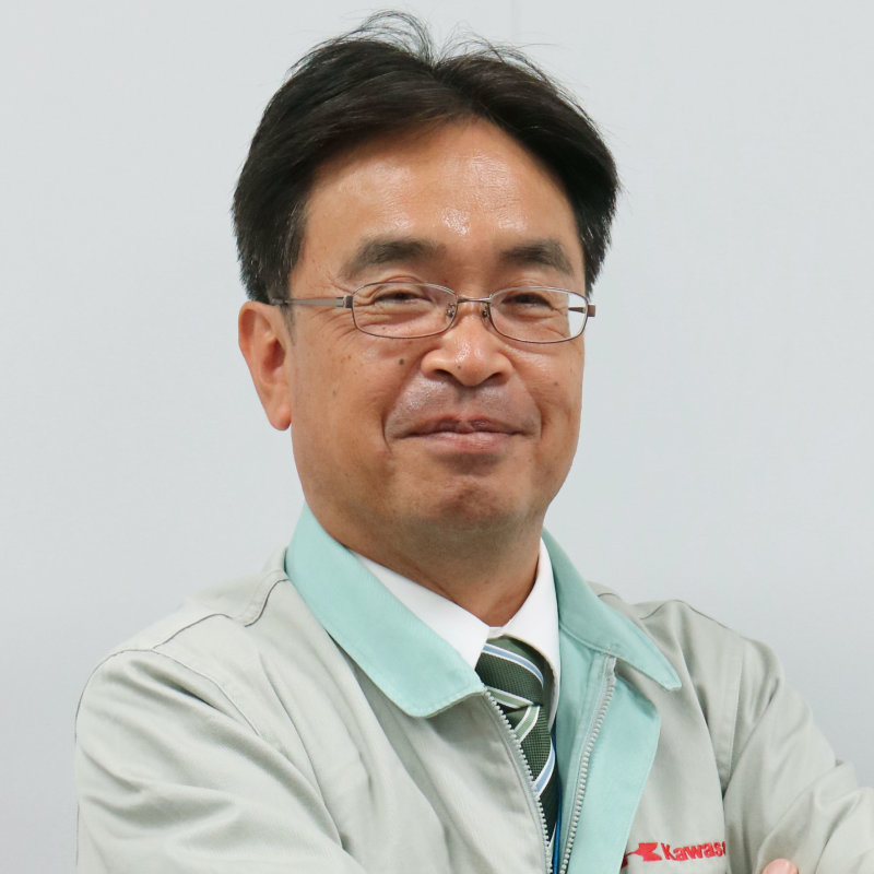
Cryogenic Storage System Department Chemical Plant & Cryogenic Storage System,
Engineering Division Plant & Infrastructure Company,
Kawasaki Heavy Industries, Ltd.
Technical Innovation Integrating Design, Manufacturing and Construction
Kawasaki entered the LNG tank business in the 1980s, and has steadily built up its track record, by now having manufactured and constructed 21 aboveground tanks and 7 in-ground tanks. In recent years, Kawasaki has been working hard in building tanks in the new construction and expansion of LNG receiving terminals and now receives orders which place it as one of the leaders.
This project has been a landmark job for the Kawasaki LNG tank business. This is not just because we were able to advance our technology but also because the three departments of design, manufacturing and construction came together in groundbreaking technical development. For example, the Harima Works helped research on-site construction problems and made the panels larger to shorten the construction time. The highly precise manufacturing technology will enable our design staff to continue to take on new challenges.
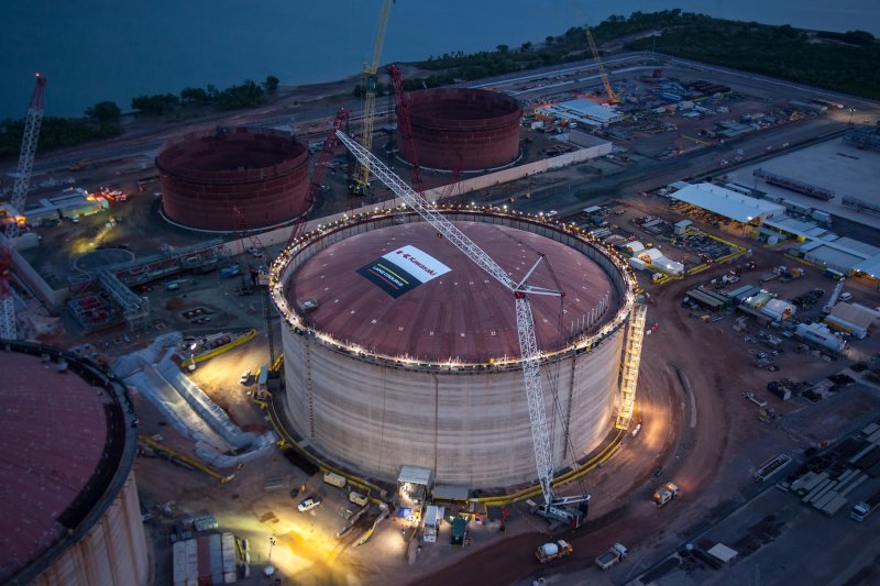
In Japan, further demand is expected for the expansion of tanks and replacement of old tanks. Also, LNG is being increasingly adopted overseas, especially in Asia. Kawasaki has been building experience with technology licensing in places such as South Korea, China, Europe, and South America and also is undertaking engineering, procurement and construction (EPC) for tank construction in Australia and Taiwan. We would like to use this experience to begin overseas expansion in earnest as we work three-in-one to create technical innovation and improve our project management capabilities.
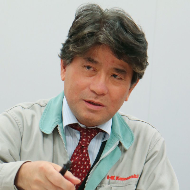
Design Section 1
Cryogenic Storage System Department
Chemical Plant & Cryogenic Storage System Engineering Division
Plant & Infrastructure Company
Kawasaki Heavy Industries, Ltd.
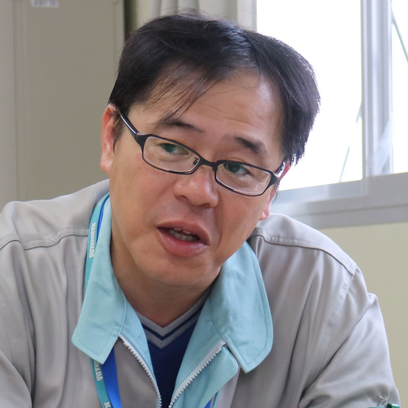
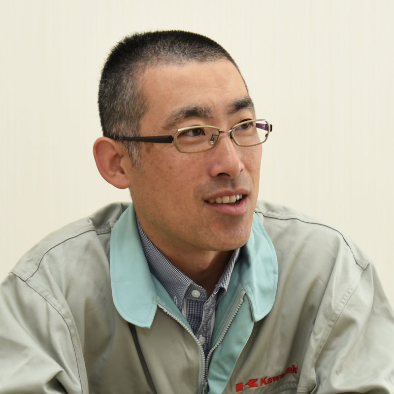
Production and Engineering Section 1
Plant & Infrastructure Company
Kawasaki Heavy Industries, Ltd.
