Accommodating the Energy Supply Needs of the Next Era: Kawasaki’s Hydrogen Liquefaction System
Hydrogen gas, which has gained attention in recent years as the next-generation clean energy source, is difficult to transport and store in large volumes. To overcome these challenges, Kawasaki developed the first industrial hydrogen liquefaction plant in Japan. This article presents the mechanisms and features of the facilities as the foundation of the coming hydrogen-based society.
Key Infrastructure that Enables Mass Transport of Hydrogen
Hydrogen is considered the “ultimate clean energy” because water is the only byproduct of its use. To advance the utilization of this eco-friendly energy, Kawasaki has been pursuing its mission of establishing a hydrogen energy supply chain and developing technologies for each of the four stages of the supply chain flow: production, transportation, storage, and use.
A hydrogen liquefaction system liquefies hydrogen gas by lowering its temperature to -253°C. Although hydrogen gas is light-weight, it is extremely bulky, making transport in its gaseous state quite difficult. Liquefaction reduces that volume to approximately 1/800 of the gaseous state, making mass transport far more efficient. A liquefaction system is therefore considered the key piece of infrastructure needed to achieve the mass transport of hydrogen.
A demonstration plant located at Kawasaki’s Harima Works is the first domestically-produced facility to perform hydrogen liquefaction, producing five tons of liquefied hydrogen per day.
As a result of a series of demonstration operations which commenced in 2014, Kawasaki has developed an extensive range of technological innovations, which include: 1. Design technology for liquefaction procedure and operational control; 2. Air-tight, high-insulation construction of the cold box (a solid cylinder enclosing the liquefier and its components); 3. Expansion turbines featuring high-speed rotation, achieving high efficiency, maintenance-free operation, and highly-purified liquefied gas; and 4. A control system which maintains the purity of the liquefied gas, and various other technologies for overall construction and maintenance for the system.
This plant was designed, developed, and constructed by Kawasaki and boasts three years of accident- and injury-free operations. The expertise gained in developing and operating this facility - so sophisticated that it is often described as “composite art” - will surely serve as the basis for our future hydrogen-based society.
The First Industrial, Domestically-Developed Hydrogen Liquefaction System
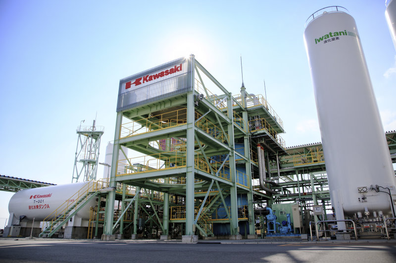
The demonstration plant commenced operations in November 2014 at Harima Works (located in Hyogo Prefecture, Japan). The cold box (the blue cylinder) housing the liquefier is placed behind the tower. The storage tank for liquefied hydrogen sits on the left. The accident- and injury-free operations experienced to date in this demonstration plant have increased Kawasaki’s safety expertise.
Liquefaction Procedure Underlying Principle: Using Hydrogen to Cool Hydrogen
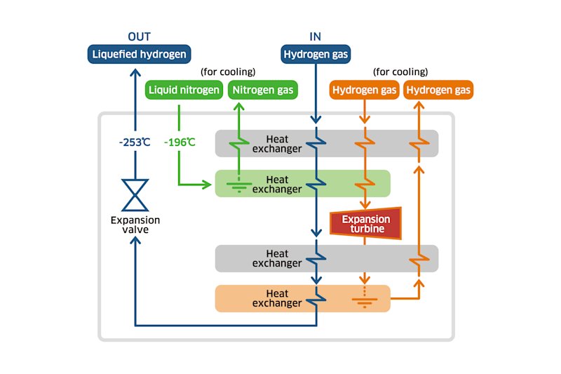
Hydrogen gas liquefies when heat exchangers remove heat to lower its temperature to -253°C. To achieve that, our demonstration plant adopts the Claude cycle, whereby, separated from the feed gas (hydrogen), nitrogen gas and the hydrogen gas used for cooling circulate through several heat exchangers and cool the feed gas to its liquefaction temperature.
The principle behind this system - using hydrogen to cool hydrogen - is not a new one, but this is the first time that an industrial facility for hydrogen liquefaction has been designed and constructed in Japan, using domestically-developed technologies alone.
Expansion Turbine A Turbine Packed with Kawasaki’s Specialized Rotating Machinery Technology
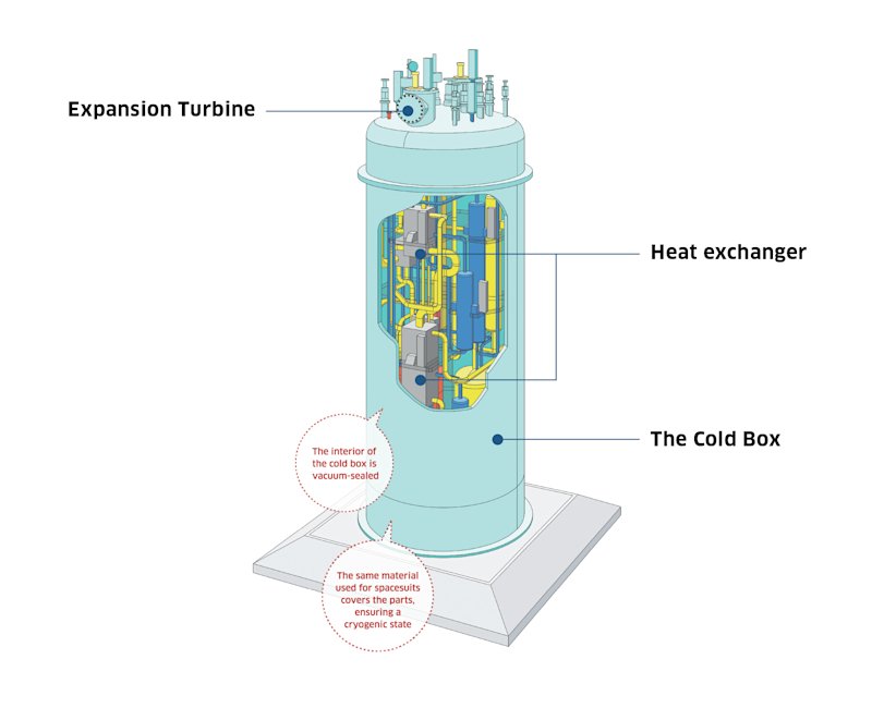
Two expansion turbines are used at the last stage of liquefaction. Feed gas that was pre-cooled to -196℃ via heat exchangers undergoes a pressure drop and further temperature reduction as it passes through an expansion turbine, resulting in liquefaction at -253℃.
The rotor of the turbine, which is only a few centimeters in diameter and ten-plus centimeters in length, is about the size of a car engine’s turbocharger. This tiny section, however, rotates at an ultra-high speed of more than 100,000 rpm with its two hydrogen gas bearings. It is indeed a masterpiece of Kawasaki’s high-speed rotating machinery technology.
Because hydrogen gas bearings are used for the floating of the shaft instead of conventional oil-lubricated bearings, impurities such as oil never enter the system, resulting in highly-pure liquefied gas. Also, because they are contact-free, no maintenance is ever required.

The Cold Box A Vessel Clad in a Satellite-Worthy “Robe”
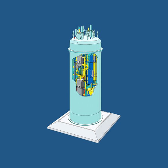
The heat exchangers and piping for liquefaction are housed in a steel cylinder called “the cold box.” Four meters in diameter and 12 meters in height, the cold box is a showcase of Kawasaki’s superior technologies: the interior of the cryogenic unit is vacuum-sealed for insulation from outside air. To maintain this state and to ensure that no leakage occurs, the sealing and welding of parts uses highly-precise and highly-sophisticated machining procedures.
In order to improve insulation performance by reducing radiant heat emitted from various parts which might affect the heat exchangers and piping, all parts are covered with the same type of metallic, super-insulation sheets used for satellites and spacesuits. Control of impurities is another key factor that achieves complete sterility throughout the process of system construction.

Hydrogen Design Section
Hydrogen System Engineering Department
Cryogenic System Engineering Division
Plant & Infrastructure Company
Kawasaki Heavy Industries, Ltd.

Technology Development Department
Hydrogen Project Development Center
Corporate Technology Division
Kawasaki Heavy Industries, Ltd.

